
Start with the clear-zone task, not a pad dimension
A useful brief explains who needs a clear reflected area and where that area sits on the installed mirror. Mark the user centreline or vanity position, the target clear-zone width and height, and any room-type differences. The supplier can then review a suitable demister-pad layout for the selected mirror construction instead of treating one pad size as universal.
- Application and room type
- Mirror width, height, orientation and user zone
- Target clear-zone position and approximate extent
- Drawing, product or sample reference
Map exclusions before proposing coverage
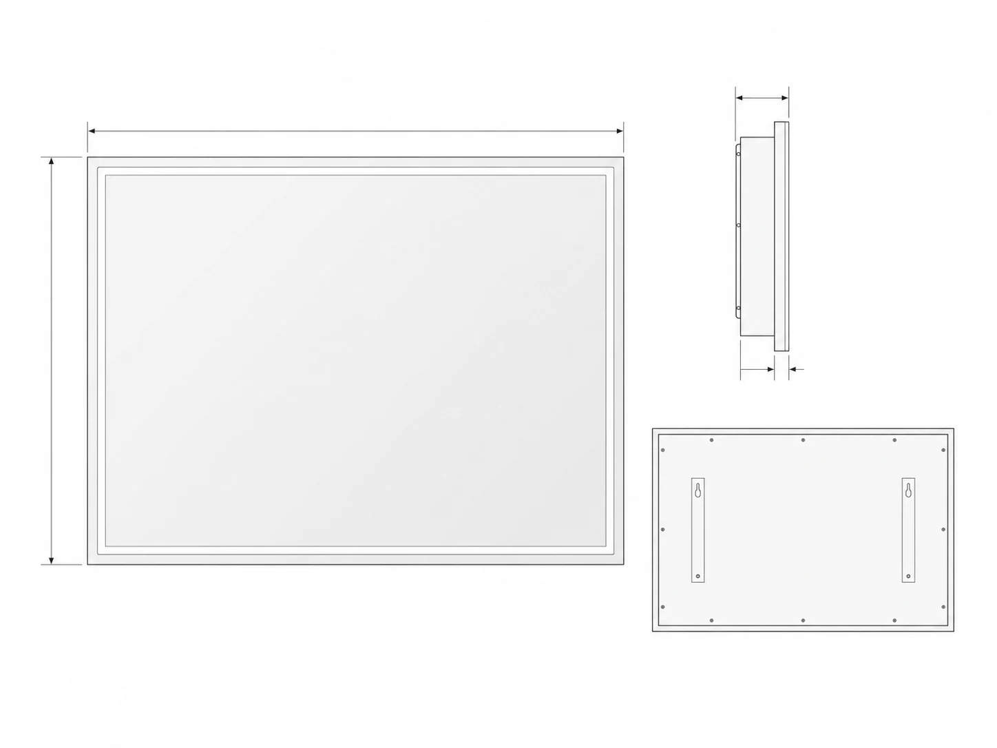
Show the demister zone on the rear-layout drawing with the light path, touch or sensor areas, driver and junction locations, fixing points, hanging hardware, edge clearances and other construction features. Ask the supplier to return conflicts and a revised layout. The final clearance and attachment rules depend on the selected construction and component specification.
- Perimeter light or frame geometry
- Touch, sensor and indicator areas
- Driver, connection and rear-component zones
- Mounting points, brackets and service access
- Supplier-confirmed edge and component clearances
Define the control and power relationship
State whether anti-fog should operate with the mirror light, through an independent mirror control or through another reviewed sequence. Record the intended indicator, default state, memory expectation and result after supply is switched off and restored. Connect this sequence to the room electrical plan and destination-market review rather than assuming the same behaviour across every model.
Keep performance evidence configuration-specific
A larger quoted pad or a higher electrical value is not proof of a better real-world clear zone. Ask what evidence will be returned for the selected mirror size, pad layout, room condition and operating sequence. Treat wattage, temperature, warm-up behaviour, protection method, electrical compatibility, testing and documentation as supplier-confirmed items for the final configuration.
Use the sample to verify the intended clear zone
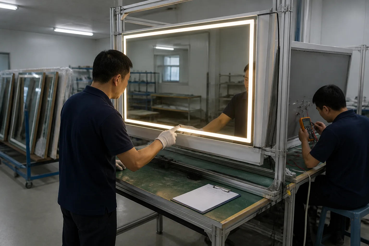
Review the selected sample in an agreed condition and record the starting state, operating time, visible clearing pattern, control sequence, power cycle and any unaffected edge areas. Tie observations to the product code, rear-layout drawing and sample revision. The result supports approval of that configuration; it does not become a universal performance claim for every size or room.
- Sample and drawing revision
- Starting room and mirror condition
- Control action, indicator and power-cycle result
- Observed clear-zone pattern and open areas
- Required drawing, instruction or component changes
Send a demister-ready RFQ
Share the application, destination market, mirror dimensions, user or vanity reference, target clear zone, proposed control sequence, room power assumptions, rear-layout constraints, quantity and sample stage. Ask the supplier to return the proposed pad layout, unsupported assumptions, open electrical or documentation questions and the sample evidence plan. Final engineering, compliance scope, price, MOQ, production schedule, warranty and delivery terms are confirmed for the selected configuration and written quotation.